Overview Link to heading
The Dynamic Multipoint VPN (DMVPN) feature allows users to scale IPSec VPNs by combining Generic Routing Encapsulation (GRE) tunnels, IPSec encryption, and Next Hop Resolution Protocol (NHRP).
DMVPN works according to the following rules: Each spoke has a permanent IPSec tunnel to the hub, not to the other spokes.
- When a spoke needs to send a packet to a private network on another spoke, it queries the NHRP server for the public address of the destination spoke.
- After having the public address, it can initiate a dynamic IPSec tunnel to the target spoke.
- The spoke-to-spoke tunnel is built over the multipoint GRE (mGRE) interface.
- When the spoke-to-spoke tunnel is established, packets use the tunnel instead of the spoke-to-hub tunnel.
Definition Link to heading
- NHRP: A client and server protocol where the hub is the server and the spokes are the clients. The hub maintains an NHRP database of the public addresses of the each spoke.
- mGRE Tunnel Interface: Allows a single GRE interface to support multiple IPSec tunnels and simplifies the size and complexity of the configuration.
Note:
- After a amount of inactivity on the spoke-to-spoke tunnels, the router will tear down those tunnels to save resources (IPSec security associations [SA]).
- The traffic profile should follow the 80-20% rule: 80% is spoke-to-hub traffic, and 20% is spoke-to-spoke traffic.
Task 1 Link to heading
Configure mGRE and NHRP for basic DMVPN
Configuration Link to heading
- In mGRE, we do not need to specify a tunnel destination.
- In spoke’s tunnel, there must be a map between NHRP Server address and NBMA address.
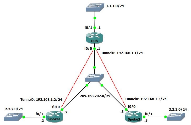
hostname Hub
int f0/0
    ip address 209.168.202.1 255.255.255.248
    no shut
int f0/1
    ip address 1.1.1.1 255.255.255.0
    no shut
int tunnel 0
    ip address 192.168.1.1 255.255.255.0
    tunnel source f0/0
    tunnel mode gre multipoint
    ip nhrp network-id 1
hostname Spoke1
int f0/0
    ip address 209.168.202.2 255.255.255.248
    no shut
int f0/1
    ip address 2.2.2.2 255.255.255.0
    no shut
int tunnel 0
    ip address 192.168.1.2 255.255.255.0
    tunnel source f0/0
    tunnel mode gre multipoint
    ip nhrp nhs 192.168.1.1
    ip nhrp map 192.168.1.1 209.168.202.1
    ip nhrp network-id 1
hostname Spoke2
int f0/0
    ip address 209.168.202.3 255.255.255.248
    no shut
int f0/1
    ip address 3.3.3.3 255.255.255.0
    no shut
int tunnel 0
    ip address 192.168.1.3 255.255.255.0
    tunnel source f0/0
    tunnel mode gre multipoint
    ip nhrp nhs 192.168.1.1
    ip nhrp map 192.168.1.1 209.168.202.1
    ip nhrp network-id 1
Task 2 Link to heading
Configure authentication for NHRP and tunnel key between Hub and Spokes.
Configuration Link to heading
Hub/Spoke1/Spoke2(config)#
int tunnel 0
    ip nhrp authentication CISCO123
    tunnel key 0
Task 3 Link to heading
- Configure DMVPN to allow multicast
- Then configure EIGRP to form neighbor between Hub and Spokes via tunnels.
Configuration Link to heading
- By default, DMVPN allows only unicast => enable multicast by mapping to the NBMA address of Hub.
- Disable split-horizon on Hub to allow Spokes learn routes of each other.
- Using the command
no ip next-hop-self eigrp 100to not modify the next-hop value of EIGRP routes on Hub => allow Spokes send packets directly to each other.
Hub(config)#
int tunnel 0
    ip nhrp map multicast dynamic
    no ip split-horizon eigrp 100
    no ip next-hop-self eigrp 100
router eigrp 100
    no auto
    network 1.1.1.0 0.0.0.255
    network 192.168.1.0 0.0.0.255
Spoke1(config)#
int tunnel 0
    ip nhrp map multicast 209.168.202.1
router eigrp 100
    no auto
    network 2.2.2.0 0.0.0.255
    network 192.168.1.0 0.0.0.255
Spoke2(config)#
int tunnel 0
    ip nhrp map multicast 209.168.202.1
router eigrp 100
    no auto
    network 3.3.3.0 0.0.0.255
    network 192.168.1.0 0.0.0.255
Verification Link to heading
Hub# show ip eigrp nei
EIGRP-IPv4 Neighbors for AS(100)
H   Address                 Interface              Hold Uptime   SRTT   RTO  Q  Seq
                                                   (sec)         (ms)       Cnt Num
1   192.168.1.3             Tu0                      13 00:00:41   61  1512  0  4
0   192.168.1.2             Tu0                      13 00:01:03   70  1512  0  3

Spoke1# show ip route eigrp
      1.0.0.0/24 is subnetted, 1 subnets
D        1.1.1.0 [90/27008000] via 192.168.1.1, 00:00:17, Tunnel0
      3.0.0.0/24 is subnetted, 1 subnets
D        3.3.3.0 [90/28288000] via 192.168.1.3, 00:00:17, Tunnel0
Task 4 Link to heading
No EIGRP, configure OSPF to form neighbor between Hub and Spokes via tunnels.
Configuration Link to heading
By default, when OSPF is enabled, the network type of tunnel interface is point-to-point.
=> Change it to point-to-multipoint or broadcast, if not the OPSF will be flapping.
=> Broadcast is more preferable than point-to-multipoint. Because OSPF does not support next-hop-self command, with broadcast, the next hop will be redirected to other Spokes instead of Hub.
Hub# show ip ospf int tun 0
Tunnel0 is administratively down, line protocol is down
  Internet Address 192.168.1.0/24, Area 0, Attached via Interface Enable
  Process ID 100, Router ID 1.1.1.1, Network Type POINT_TO_POINT, Cost: 1000
  Topology-MTID    Cost    Disabled    Shutdown      Topology Name
        0           1000      no          no            Base
  Enabled by interface config, including secondary ip addresses
  Transmit Delay is 1 sec, State DOWN
  Timer intervals configured, Hello 10, Dead 40, Wait 40, Retransmit 5
    oob-resync timeout 40
Configuration Link to heading
Hub(config)#
no router eigrp 100
router ospf 1
int f0/1
    ip ospf 1 area 0
int tunnel 0
    ip ospf 1 area 0
    ip ospf network broadcast
Spoke1(config)#
no router eigrp 100
router ospf 1
int f0/1
    ip ospf 1 area 0
int tunnel 0
    ip ospf 1 area 0
    ip ospf network broadcast
    ip ospf priority 0
Spoke2(config)#
no router eigrp 100
router ospf 1
int f0/1
    ip ospf 1 area 0
int tunnel 0
    ip ospf 1 area 0
    ip ospf network broadcast
    ip ospf priority 0
Task 5 Link to heading
Configure IP Sec for DMVPN
Configuration Link to heading
Hub(config)#
# Create an ISAKMP policy for Phase 1 negotiations
crypto isakmp policy 10
    hash md5
    authentication pre-share
# Add dynamic pre-shared keys for all the remote VPN routers
crypto isakmp key CISCO123 address 0.0.0.0 0.0.0.0
# Create the Phase 2 policy for actual data encryption
crypto ipsec transform-set strong esp-3des esp-md5-hmac
# Create an IPSec profile to be applied dynamically to the GRE over IPSec tunnels
crypto ipsec profile DMVPN
    set security-association lifetime seconds 900
    set transform-set strong
int tunnel 0
    ip mtu 1440
    tunnel protection ipsec profile DMVPN
Spoke1(config)#
crypto isakmp policy 10
    hash md5
    authentication pre-share
crypto isakmp key CISCO123 address 0.0.0.0 0.0.0.0
crypto ipsec transform-set strong esp-3des esp-md5-hmac
crypto ipsec profile DMVPN
    set security-association lifetime seconds 900
    set transform-set strong
int tunnel 0
    ip mtu 1440
    tunnel protection ipsec profile DMVPN
Spoke2(config)#
crypto isakmp policy 10
    hash md5
    authentication pre-share
crypto isakmp key CISCO123 address 0.0.0.0 0.0.0.0
crypto ipsec transform-set strong esp-3des esp-md5-hmac
crypto ipsec profile DMVPN
    set security-association lifetime seconds 900
    set transform-set strong
int tunnel 0
    ip mtu 1440
    tunnel protection ipsec profile DMVPN
Verification Link to heading
- show crypto engine connection active: Display the total encrypts and decrypts per SA.
- show crypto ipsec sa: Display the stats on the active tunnels.
- show crypto isakmp sa: Display the state for the the ISAKMP SA.
Debug Link to heading
- debug nhrp: Enable NHRP debugging
- debug nhrp packet: Display a dump of NHRP packets.
- debug crypto ipsec: Display IPSec events.
- debug crypto isakmp: Display messages about Internet Key Exchange (IKE) events.
- debug crypto engine: Display information from the crypto engine.