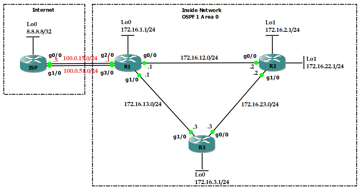
Task 1 Link to heading
- Configure OSPF area 0 in Inside Network to make sure Loopback interfaces can ping each other.
- Configure OSPF so that R1 goes to R2 via R1-R2 link, but R2 goes to R1 via R3.
Configuration Link to heading
hostname R1
int l0
    ip add 172.16.1.1 255.255.255.0
int g0/0
    no shut
    ip add 172.16.12.1 255.255.255.0
int g1/0
    no shut
    ip add 172.16.13.1 255.255.255.0
int g2/0
    no shut
    ip add 100.0.15.1 255.255.255.0
int g3/0
    no shut
    ip add 100.0.51.1 255.255.255.0
router ospf 1
    router-id 1.1.1.1
int l0
    ip ospf 1 area 0
int g0/0
    ip ospf 1 area 0
int g1/0
    ip ospf 1 area 0
hostname R2
int l0
    ip add 172.16.2.1 255.255.255.0
int l1
    ip add 172.16.22.1 255.255.255.0
int g0/0
    no shut
    ip add 172.16.12.2 255.255.255.0
int g1/0
    no shut
    ip add 172.16.23.2 255.255.255.0
router ospf 1
    router-id 2.2.2.2
int l0
    ip ospf 1 area 0
int l1
    ip ospf 1 area 0
int g0/0
    ip ospf 1 area 0
    ip ospf cost 10
int g1/0
    ip ospf 1 area 0
hostname R3
int l0
    ip add 172.16.3.1 255.255.255.0
int g0/0
    no shut
    ip add 172.16.23.3 255.255.255.0
int g1/0
    no shut
    ip add 172.16.13.3 255.255.255.0
router ospf 1
    router-id 3.3.3.3
int l0
    ip ospf 1 area 0
int g0/0
    ip ospf 1 area 0
int g1/0
    ip ospf 1 area 0
hostname ISP
int l0
    ip add 8.8.8.8 255.255.255.255
int g0/0
    no shut
    ip add 100.0.15.5 255.255.255.0
int g1/0
    no shut
    ip add 100.0.51.5 255.255.255.0
Verification Link to heading
R1# show ip route ospf
      172.16.0.0/16 is variably subnetted, 9 subnets, 2 masks
O        172.16.2.1/32 [110/2] via 172.16.12.2, 00:02:20, GigabitEthernet0/0
O        172.16.22.1/32 [110/2] via 172.16.12.2, 00:00:11, GigabitEthernet0/0
O        172.16.3.1/32 [110/2] via 172.16.13.3, 00:01:59, GigabitEthernet1/0
O        172.16.23.0/24 [110/2] via 172.16.13.3, 00:01:59, GigabitEthernet1/0
                        [110/2] via 172.16.12.2, 00:02:10, GigabitEthernet0/0
R2# show ip route ospf
      172.16.0.0/16 is variably subnetted, 9 subnets, 2 masks
O        172.16.1.1/32 [110/3] via 172.16.23.3, 00:01:50, GigabitEthernet1/0
O        172.16.3.1/32 [110/2] via 172.16.23.3, 00:01:50, GigabitEthernet1/0
O        172.16.13.0/24 [110/2] via 172.16.23.3, 00:01:50, GigabitEthernet1/0
Task 2 Link to heading
- Configure 2 static routes to 8.8.8.8 on R1.
- R1 uses 100.0.15.0/24 as PRIMARY link, while using 100.0.51.0/24 as BACKUP link.
- Using track IP SLA to make sure the BACKUP link working.
- Advertise a default fault route to inside network.
Configuration Link to heading
R1(config)#
ip sla 1
    icmp-echo 100.0.15.5 source-interface g2/0
    frequency 5
ip sla schedule 1 start now life forever
track 1 ip sla 1
    delay down 5 up 5
ip route 8.8.8.8 255.255.255.255 100.0.15.5 track 1
ip route 8.8.8.8 255.255.255.255 100.0.51.5 10
router ospf 1
    default-information originate always
Verification Link to heading
R1# show ip route static
      8.0.0.0/32 is subnetted, 1 subnets
S        8.8.8.8 [1/0] via 100.0.15.5
R2# show ip route ospf
Gateway of last resort is 172.16.23.3 to network 0.0.0.0
O*E2  0.0.0.0/0 [110/1] via 172.16.23.3, 00:00:11, GigabitEthernet1/0
      172.16.0.0/16 is variably subnetted, 9 subnets, 2 masks
O        172.16.1.1/32 [110/3] via 172.16.23.3, 00:19:23, GigabitEthernet1/0
O        172.16.3.1/32 [110/2] via 172.16.23.3, 00:19:23, GigabitEthernet1/0
O        172.16.13.0/24 [110/2] via 172.16.23.3, 00:19:23, GigabitEthernet1/0
Task 3 Link to heading
- Configure NAT on R1 so that host 172.16.22.1 will be NAT-ed to public IP address 100.0.15.22 and use the PRIMARY link to connect Internet.
- Make sure that if the PRIMARY link is down, host 172.16.22.1 will be NAT-ed to 100.0.51.22 and use the BACKUP link to connect Internet.
Answer:
- We cannot configure 2 static NAT which translate the same source IP address:
R1(config)#ip nat inside source static 172.16.22.1 100.0.15.22
R1(config)#ip nat inside source static 172.16.22.1 100.0.51.22
%NAT: 172.16.22.1 already mapped (172.16.22.1 -> 100.0.15.22)
- We have to use route-map with match interface for NAT redundancy.
Configuration Link to heading
R1(config)#
access-list 1 permit host 172.16.22.1
route-map PRIMARY permit 10
    match ip add 1
    match int g2/0
route-map BACKUP permit 10
    match ip add 1
    match int g3/0
ip nat inside source static 172.16.22.1 100.0.15.22 route-map PRIMARY
ip nat inside source static 172.16.22.1 100.0.51.22 route-map BACKUP
int g0/0
    ip nat inside
int g1/0
    ip nat inside
int g2/0
    ip nat outside
int g3/0
    ip nat outside
Verification Link to heading
R2#trace
Protocol [ip]:
Target IP address: 8.8.8.8
Source address: 172.16.22.1
Numeric display [n]:
Timeout in seconds [3]:
Probe count [3]:
Minimum Time to Live [1]:
Maximum Time to Live [30]:
Port Number [33434]:
Loose, Strict, Record, Timestamp, Verbose[none]:
Type escape sequence to abort.
Tracing the route to 8.8.8.8
VRF info: (vrf in name/id, vrf out name/id)
  1 172.16.23.3 44 msec 20 msec 20 msec
  2 172.16.13.1 32 msec 32 msec 28 msec
  3 100.0.15.5 52 msec 52 msec 48 msec
R1#show ip nat trans
Pro Inside global      Inside local       Outside local      Outside global
udp 100.0.15.22:49160  172.16.22.1:49160  8.8.8.8:33440      8.8.8.8:33440
udp 100.0.15.22:49160  172.16.22.1:49160  100.0.15.5:33440   100.0.15.5:33440
udp 100.0.15.22:49161  172.16.22.1:49161  8.8.8.8:33441      8.8.8.8:33441
udp 100.0.15.22:49161  172.16.22.1:49161  100.0.15.5:33441   100.0.15.5:33441
udp 100.0.15.22:49162  172.16.22.1:49162  8.8.8.8:33442      8.8.8.8:33442
Test by delete PRIMARY link between R1 and ISP.
R2#trace
Protocol [ip]:
Target IP address: 8.8.8.8
Source address: 172.16.22.1
Numeric display [n]:
Timeout in seconds [3]:
Probe count [3]:
Minimum Time to Live [1]:
Maximum Time to Live [30]:
Port Number [33434]:
Loose, Strict, Record, Timestamp, Verbose[none]:
Type escape sequence to abort.
Tracing the route to 8.8.8.8
VRF info: (vrf in name/id, vrf out name/id)
  1 172.16.23.3 44 msec 20 msec 16 msec
  2 172.16.13.1 32 msec 32 msec 32 msec
  3 100.0.51.5 40 msec 48 msec
R1#show ip nat trans
Pro Inside global      Inside local       Outside local      Outside global
udp 100.0.51.22:49170  172.16.22.1:49170  8.8.8.8:33440      8.8.8.8:33440
udp 100.0.51.22:49171  172.16.22.1:49171  8.8.8.8:33441      8.8.8.8:33441
udp 100.0.51.22:49171  172.16.22.1:49171  100.0.51.5:33441   100.0.51.5:33441
udp 100.0.51.22:49172  172.16.22.1:49172  8.8.8.8:33442      8.8.8.8:33442
udp 100.0.51.22:49172  172.16.22.1:49172  100.0.51.5:33442   100.0.51.5:33442
Task 4 Link to heading
- Configure PAT (NAT overload) on R1 so that other inside networks will be NAT-ed to IP address of g2/0.
- Make sure that if the PRIMARY link is down, other inside networks will be NAT-ed to IP address of g3/0.
Configuration Link to heading
R1(config)#
access-list 2 permit any
route-map OTHER_PRIMARY permit 10
    match ip add 2
    match int g2/0
route-map OTHER_BACKUP permit 10
    match ip add 2
    match int g3/0
ip nat inside source route-map OTHER_PRIMARY int g2/0 overload
ip nat inside source route-map OTHER_BACKUP int g3/0 overload
Verification Link to heading
R3#trace
Protocol [ip]:
Target IP address: 8.8.8.8
Source address: 172.16.3.1
Numeric display [n]:
Timeout in seconds [3]:
Probe count [3]:
Minimum Time to Live [1]:
Maximum Time to Live [30]:
Port Number [33434]:
Loose, Strict, Record, Timestamp, Verbose[none]:
Type escape sequence to abort.
Tracing the route to 8.8.8.8
VRF info: (vrf in name/id, vrf out name/id)
  1 172.16.13.1 68 msec 24 msec 20 msec
  2 100.0.15.5 44 msec 40 msec 40 msec
Test by delete PRIMARY link between R1 and ISP.
R3#trace
Protocol [ip]:
Target IP address: 8.8.8.8
Source address: 172.16.3.1
Numeric display [n]:
Timeout in seconds [3]:
Probe count [3]:
Minimum Time to Live [1]:
Maximum Time to Live [30]:
Port Number [33434]:
Loose, Strict, Record, Timestamp, Verbose[none]:
Type escape sequence to abort.
Tracing the route to 8.8.8.8
VRF info: (vrf in name/id, vrf out name/id)
  1 172.16.13.1 40 msec 20 msec 20 msec
  2 100.0.51.5 32 msec 44 msec
Task 5 Link to heading
- Configure uRPF on R1 so that R1 will block all packets whose source IP addresses are inside network, coming from Internet.
- Configure uRPF on R1 so that R1 will block all packets whose source IP addresses are not inside networks, coming from inside networks.
Answer:
- Configure uRPF strict mode at outside interfaces.
- Configure uRPF loose mode at inside interfaces because R2 uses R3 to reach R1, while R1 use the link R1-R2 to reach R2.
Configuration Link to heading
R1(config)#
access-list 100 deny ip any any log
int g0/0
    ip verify unicast source reachable-via any 100
int g1/0
    ip verify unicast source reachable-via any 100

int g2/0
    ip verify unicast source reachable-via rx allow-default 100
int g3/0
    ip verify unicast source reachable-via rx allow-default 100
Verification Link to heading
Test by create a fake IP address from ISP
IPS(config)#
int l1
    ip add 172.16.1.1 255.255.255.0
ip route 172.16.2.0 255.255.255.0 100.0.15.1

ISP#ping 172.16.2.1 source 172.16.1.1
R1#
*Jan 30 11:03:52.615: %SEC-6-IPACCESSLOGDP: list 100 denied icmp 172.16.1.1 -> 172.16.2.1 (0/0), 5 packets

R1#show ip int g2/0
  Input features: uRPF, NAT Outside, MCI Check
  Output features: Post-routing NAT Outside
  WCCP Redirect outbound is disabled
  WCCP Redirect inbound is disabled
  WCCP Redirect exclude is disabled
  IP verify source reachable-via RX, allow default, ACL 100
   44 verification drops
   0 suppressed verification drops
   0 verification drop-rate