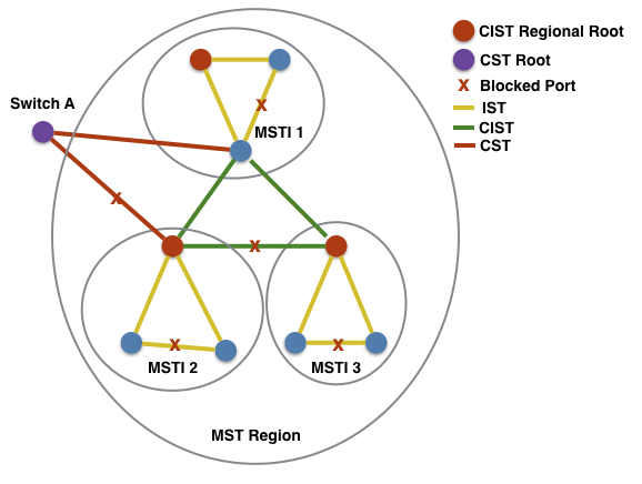
MST concept Link to heading
Lab Objectives Link to heading
- MST implementation.
- Additional technology: VTP version 3 propagate the MST region.
Task 1 Link to heading
- Configure VTP on all switches:
- VTP domain SWITCH.
- VTP mode server.
- VTP verison 2.
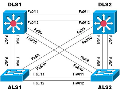
- Configure explicitly interfaces F0/7 through F0/12 as 802.1Q trunk ports on all switches and disable DTP.
- Change the native VLAN to VLAN 666 and do not allow VLAN 1 and 999 on all trunks.
- Configure these following VLANs on only DLS1:
- VLAN 99 - name MANAGEMENT.
- VLAN 100 - name SERVERS.
- VLAN 110 - name GUEST.
- VLAN 120 - name OFFICE.
- VLAN 999 - name PARKING_LOT (suspend this VLAN).
- VLAN 666 - name NATIVE_DO_NOT_USE.
Configuration Link to heading
hostname DLS1
vtp domain SWITCH
vtp version 2
int range f0/7-12
    sw trunk encap dot1Q
    sw trunk native vlan 666
    sw trunk allow vlan except 1,999
    sw mode trunk
    sw nonegotiate
vlan 99
    name MANAGEMENT
vlan 100
    name SERVERS
vlan 110
    name GUEST
vlan 120
    name OFFICE
vlan 999
    name PARKING_LOT
    state suspend
vlan 666
    name NATIVE_DO_NOT_USE
hostname DLS2
vtp domain SWITCH
vtp version 2
int range f0/7-12
    sw trunk encap dot1Q
    sw trunk native vlan 666
    sw trunk allow vlan except 1,999
    sw mode trunk
    sw nonegotiate
hostname ALS1
vtp domain SWITCH
vtp version 2
int range f0/7-12
    sw trunk native vlan 666
    sw trunk allow vlan except 1,999
    sw mode trunk
    sw nonegotiate
hostname ALS2
vtp domain SWITCH
vtp version 2
int range f0/7-12
    sw trunk native vlan 666
    sw trunk allow vlan except 1,999
    sw mode trunk
    sw nonegotiate
Verification Link to heading
ALS2#show vlan
VLAN Name                             Status    Ports
---- -------------------------------- --------- -------------------------------
1    default                          active    Fa0/1, Fa0/2, Fa0/3, Fa0/4
                                                Fa0/5, Fa0/6, Fa0/13, Fa0/14
                                                Fa0/15, Fa0/16, Fa0/17, Fa0/18
                                                Fa0/19, Fa0/20, Fa0/21, Fa0/22
                                                Fa0/23, Fa0/24, Gi0/1, Gi0/2
99   MANAGEMENT                       active
100  SERVERS                          active
110  GUEST                            active
120  OFFICE                           active
666  NATIVE_DO_NOT_USE                active
999  PARKING_LOT                      suspended
Task 2: Link to heading
- Manually Configure MST on both DLS1 and DLS2:
- Region Name: CCNP
- Revision Number: 1
- Instance 1: VLAN 99 and VLAN 100.
- Instance 2: VLAN 110 and VLAN 120.
- Ensure that:
- DLS1 must be root brigde for instance 1.
- DLS2 must be backup root bridge for instance 1.
- DLS2 must be root brigde for instance 2.
- DLS1 must be backup root bridge for instance 2.
Answer:
Under the mst configuration mode, the changes are not applied until you exit.
Configuration Link to heading
DLS1(config)#
spanning mode mst
spanning mst config
    name CCNP
    revision 1
    instance 1 vlan 99, 100
    instance 2 vlan 110, 120
    exit
spanning mst 1 root primary
spanning mst 2 root secondary
DLS2(config)#
spanning mode mst
spanning mst config
    name CCNP
    revision 1
    instance 1 vlan 99, 100
    instance 2 vlan 110, 120
    exit
spanning mst 1 root secondary
spanning mst 2 root primary
Verification Link to heading
DLS1#show spanning mst
##### MST0    vlans mapped:   1-98,101-109,111-119,121-4094
Bridge        address 0017.0e00.fc80  priority      32768 (32768 sysid 0)
Root          this switch for the CIST
Operational   hello time 2 , forward delay 15, max age 20, txholdcount 6
Configured    hello time 2 , forward delay 15, max age 20, max hops    20
Interface        Role Sts Cost      Prio.Nbr Type
---------------- ---- --- --------- -------- --------------------------------
Fa0/1            Desg FWD 200000    128.3    P2p
Fa0/7            Desg FWD 200000    128.9    P2p Bound(PVST)
Fa0/8            Desg FWD 200000    128.10   P2p Bound(PVST)
Fa0/9            Desg FWD 200000    128.11   P2p Bound(PVST)
Fa0/10           Desg FWD 200000    128.12   P2p Bound(PVST)
Fa0/11           Desg FWD 200000    128.13   P2p
Fa0/12           Desg FWD 200000    128.14   P2p
##### MST1    vlans mapped:   99-100
Bridge        address 0017.0e00.fc80  priority      24577 (24576 sysid 1)
Root          this switch for MST1
Interface        Role Sts Cost      Prio.Nbr Type
---------------- ---- --- --------- -------- --------------------------------
Fa0/7            Desg FWD 200000    128.9    P2p Bound(PVST)
Fa0/8            Desg FWD 200000    128.10   P2p Bound(PVST)
Fa0/9            Desg FWD 200000    128.11   P2p Bound(PVST)
Fa0/10           Desg FWD 200000    128.12   P2p Bound(PVST)
Fa0/11           Desg FWD 200000    128.13   P2p
Fa0/12           Desg FWD 200000    128.14   P2p
##### MST2    vlans mapped:   110,120
Bridge        address 0017.0e00.fc80  priority      28674 (28672 sysid 2)
Root          address 1ce8.5d1f.fc00  priority      24578 (24576 sysid 2)
              port    Fa0/11          cost          200000    rem hops 19
Interface        Role Sts Cost      Prio.Nbr Type
---------------- ---- --- --------- -------- --------------------------------
Fa0/7            Desg FWD 200000    128.9    P2p Bound(PVST)
Fa0/8            Desg FWD 200000    128.10   P2p Bound(PVST)
Fa0/9            Desg FWD 200000    128.11   P2p Bound(PVST)
Fa0/10           Desg FWD 200000    128.12   P2p Bound(PVST)
Fa0/11           Root FWD 200000    128.13   P2p
Fa0/12           Altn BLK 200000    128.14   P2p
P2p Bound (PVST) keyword shown when the device connected at the other end of the given interface is not running MST; in this case, ALS1 and ALS2 are running the default PVST.
Task 3 Link to heading
- Propagate MST database with VTP version 3 from DLS2 to ALS1.
- Ensure that DLS2 is VTP primary for MST.
Answer:
- In order to use VTP version 3 to propagate the MST region configuration to all switches in the VTP domain:
- Activate MST on all switches.
- Convert all switches to VTP version 3 and set them as servers or clients for MST.
- Designate 1 switch as the VTP primary for MST.
- VTP version 3 will synchronize only the region configuration across all switches and will not affect the STP version running on the switch.
Configuration Link to heading
DLS2(config)#
vtp version 3
vtp mode server mst

DLS2#
vtp primary mst
This system is becoming primary server for feature mst
No conflicting VTP3 devices found.
Do you want to continue? [confirm]
ALS1(config)#
spanning mode mst
vtp version 3
vtp mode server mst
Verification Link to heading
ALS1#show spanning mst
##### MST0    vlans mapped:   1-98,101-109,111-119,121-4094
Bridge        address e089.9d45.0a80  priority      32768 (32768 sysid 0)
Root          address 0017.0e00.fc80  priority      32768 (32768 sysid 0)
              port    Fa0/7           path cost     0
Regional Root address 0017.0e00.fc80  priority      32768 (32768 sysid 0)
                                      internal cost 200000    rem hops 19
Operational   hello time 2 , forward delay 15, max age 20, txholdcount 6
Configured    hello time 2 , forward delay 15, max age 20, max hops    20
Interface        Role Sts Cost      Prio.Nbr Type
---------------- ---- --- --------- -------- --------------------------------
Fa0/7            Root FWD 200000    128.7    P2p
Fa0/8            Altn BLK 200000    128.8    P2p
Fa0/9            Altn BLK 200000    128.9    P2p
Fa0/10           Altn BLK 200000    128.10   P2p
Fa0/11           Desg FWD 200000    128.11   P2p Bound(PVST)
Fa0/12           Desg FWD 200000    128.12   P2p Bound(PVST)
##### MST1    vlans mapped:   99-100
Bridge        address e089.9d45.0a80  priority      32769 (32768 sysid 1)
Root          address 0017.0e00.fc80  priority      24577 (24576 sysid 1)
              port    Fa0/7           cost          200000    rem hops 19
Interface        Role Sts Cost      Prio.Nbr Type
---------------- ---- --- --------- -------- --------------------------------
Fa0/7            Root FWD 200000    128.7    P2p
Fa0/8            Altn BLK 200000    128.8    P2p
Fa0/9            Altn BLK 200000    128.9    P2p
Fa0/10           Altn BLK 200000    128.10   P2p
Fa0/11           Desg FWD 200000    128.11   P2p Bound(PVST)
Fa0/12           Desg FWD 200000    128.12   P2p Bound(PVST)
##### MST2    vlans mapped:   110,120
Bridge        address e089.9d45.0a80  priority      32770 (32768 sysid 2)
Root          address 1ce8.5d1f.fc00  priority      24578 (24576 sysid 2)
              port    Fa0/9           cost          200000    rem hops 19
Interface        Role Sts Cost      Prio.Nbr Type
---------------- ---- --- --------- -------- --------------------------------
Fa0/7            Altn BLK 200000    128.7    P2p
Fa0/8            Altn BLK 200000    128.8    P2p
Fa0/9            Root FWD 200000    128.9    P2p
Fa0/10           Altn BLK 200000    128.10   P2p
Fa0/11           Desg FWD 200000    128.11   P2p Bound(PVST)
Fa0/12           Desg FWD 200000    128.12   P2p Bound(PVST)
An identical MST region configuration will be propagated to all switches within a VTPv3 domain, and consequently they will all form a single region. As a result, there is always a one-to-one mapping between a VTPv3 domain and an MST region.
ALS1#show spanning root
                                        Root    Hello Max Fwd
MST Instance           Root ID          Cost    Time  Age Dly  Root Port
---------------- -------------------- --------- ----- --- ---  ------------
MST0             32768 0017.0e00.fc80         0    2   20  15  Fa0/7
MST1             24577 0017.0e00.fc80    200000    2   20  15  Fa0/7
MST2             24578 1ce8.5d1f.fc00    200000    2   20  15  Fa0/9
Port costs, which are summed to find a path cost in the quest for a root bridge, are different in MST:
- 10 Mbps — 2,000,000
- 100 Mbps — 200,000
- 1 Gigabit Ethernet — 20,000
- 10 Gigabit Ethernet — 2,000